
Many modern AVR based microcontrollers use the UPDI protocol for programming. For example the 0-series of AtMegas, the 1- and 2-series of AtTinys and many of the modern AtXMegas. The advantage of UPDI is that it uses only one pin instead of four with the SPI based ISP protocol or even more when using JTAG.
The UPDI protocol is based on the UART serial protocol, but instead of separate Rx and Tx pins the UPDI pin works in "one-wire" (half-duplex) with both sides alternating in sending and receiving data.
Communication begins by the progger or debugger hardware sending a "Break Condition" - meaning it pulls the UPDI line low (UART/UPDI idle is high) for some time, followed by a SYNC character to synchonize both sides to the same baud rate - with the progger/debugger always dictating the speed. After that actual programming or debugging commands are sent and the microcontroller responds with both sides switching their sender and receiver roles as necessary by the communication exchanged.
Unfortunately most hardware that can act as a progger or debugger is somewhat expensive or complex to create. Fortunately there is a simple alternative using a cheap USB serial TTL dongle and a single resistor.
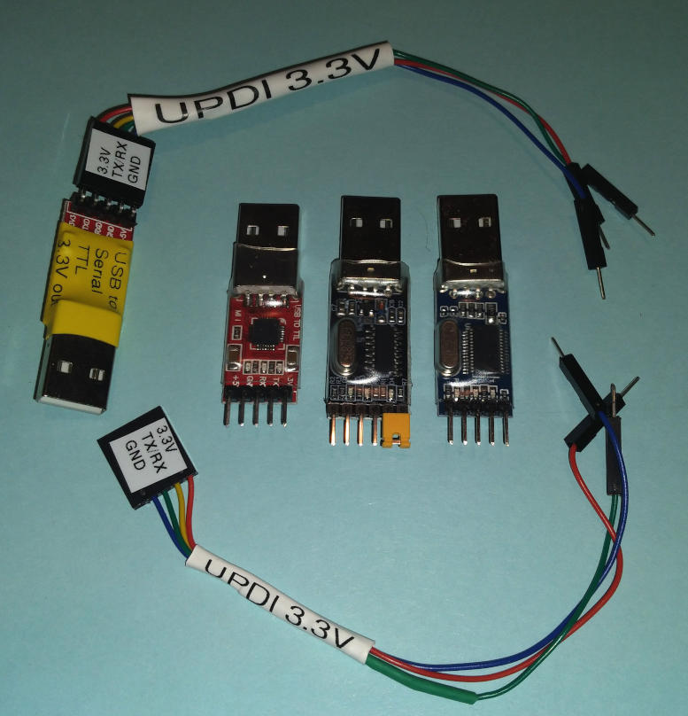
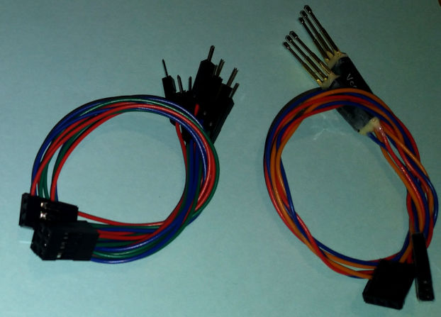
The picture on the right (Fig.1) shows some cheap USB-serial-TTL dongles as well as some simple conversion cables (the resistor is hidden underneith the shrink tube label).
Care must be taken to get a TTL level UART dongle, because the signal voltage must (roughly) match the power supply voltage. Some dongles have two power supply pins: 3.3V and 5V. Chose the one that matches the level of the Tx pin - since UART idle is High, you can simply use a multimeter to compare the signal High level with the power out pins. The microcontrollers will not care whether they are programmed while connected to 5V or 3.3V.
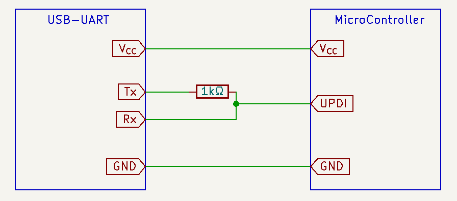
A simple UART to UPDI converter (see Fig.2 left) can be created by connecting a resistor to the Tx out pin of the UART dongle and then connecting the other side of the resistor and the Rx pin to the UPDI pin of the microcontroller, as shown in the schematic on the left. The resistor should be in the 1kΩ to 5kΩ range.
When the microcontroller is receiving this simply adds a resistor between the sending Tx pin of the dongle and the receiving UPDI pin of the microcontroller. The Rx pin of the dongle receives a copy of what the dongle is sending, but this can be easily filtered out in software. Since the UPDI pin does not require much current to flow (CMOS technology) this does not significantly impact the data quality. When the microcontroller is sending data from the UPDI pin, the Rx pin of the dongle is directly connected to UPDI and receives a clear signal, the Tx pin of the dongle is still connected via the resistor, but cannot override the UPDI signal - the resistor merely has to absorb a few mA of current every time the microcontroller sends a 0 (Low or Break) bit - this is not a problem for those two pins sourcing the current.
Technically there are a few finer points to UPDI, in which the progger is supposed to detect the internal pull-up of the microcontroller before it starts communicating. Experience shows that this can be safely ignored, connecting to a non-UPDI pin merely makes communication fail a few bits later instead.
AVRdude added support for this cheap dongle in version 7.0 - it is called "serialupdi". For example to program an AtMega4808 on a Linux system you would call it like this:
bash$ avrdude -c serialupdi -P /dev/ttyUSB0 -p m4808 -v -Uflash:w:myfirmware.hex:i
You can download statically linked binaries for a current AVRdude for the major operating systems from Arduino: https://github.com/arduino/avrdude-packing/releases/
At least on Linux it is easy to build AVRdude from sources yourself. You can find a description on how to do this on the AVRdude Wiki.
This is a PCB design that integrates the USB-serial function with the above simple UART-to-UPDI adaptor.
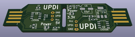
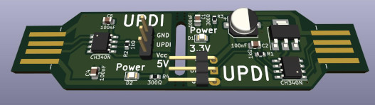
The design is based on the rather cheap CH340N chip - it is produced by WCH from China, so you may need to order it on AliExpress. The N-variant is the physically smallest and simplest variant of the chip, so this keeps the dongle quite small.
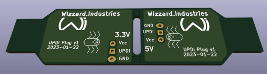
The PCB (see rendering in Fig.4 on the right) contains two variations of the dongle: one for 3.3V output and one for 5V output.
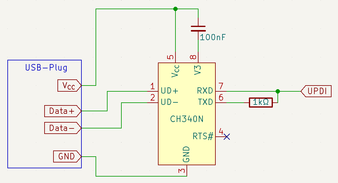
You'll find a simplified schematic of the 5V variant in Fig.3 on the left. For the 5V variant the CH340N can be supplied directly from the 5V on USB, its V3 pin has to be separated by a capacitor - 100nF is a value that will do fine, anything in the neighborhood will do. For the 3.3V variant both the Vcc and V3 pins have to be directly connected to the 3.3V output of a voltage regulator. The resistor works exactly as above, but is integrated on the PCB. Instead of separate Tx and Rx pins the PCB has a single UPDI pin.
The USB-A connector is integrated into the PCB to save on components - alternatively a micro-USB plug would have to be fitted. For USB-C some additional components (two 5.1kΩ resistors) would also be necessary.
The UPDI connector on the PCB is compatible with normal Dupont style pin headers with UPDI in the middle and Ground and the selected voltage on the outside. It should be easy to fashion a cable to connect it to the PCB. I'm in the habit of placing an identical connector next to the microcontroller, so that it can be connected with a simple cable with Dupont connectors for programming.
The finished assembly (see Fig.5, including UPDI wires) simply separates the two halves, so the user can chose which voltage is desired.
The PCB is designed using a 2-layer layout with the bottom layer functioning as ground plane.
If you want to switch to a 1-layer layout then the 3.3V version needs to be rerouted to connect the USB ground to the voltage regulator - e.g. by enlarging the two vias and using a wire.
If you have a choice of thickness go for 2.4mm or 1.6mm thick PCBs:
If possible use ENIG (gold) finish - it makes the plugs more durable. At the very least HASL (tin/nickel) finish is recommended.
The design uses the smallest CH340 package that can still be easily soldered. All resistors and LEDs are 0603 SMD types. Capacitors are 0805 for 100nF, the polarized capacitor can be any type between 3-6mm SMD. There is no particular design need for those exact sizes and types, they are just the ones I had lying around.
5V side:
3.3V side:
All values and positions are indicated on the PCB, only the front side requires soldering. All components are SMD (makes automated assembly cheaper) and at least 0603 (makes hand assembly less fiddly, you may need the help of a lens or microscope though).
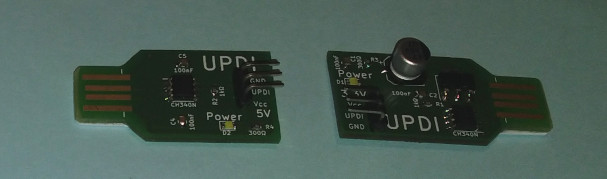
Making the USB Plug fit:
The USB-A plug is integrated in the PCB, so the PCB thickness needs to fit the USB socket. Most 2-layer PCBs have a thickness of 1.6mm, while USB-A connectors have a thickness of about 2.4mm at the connecting side.
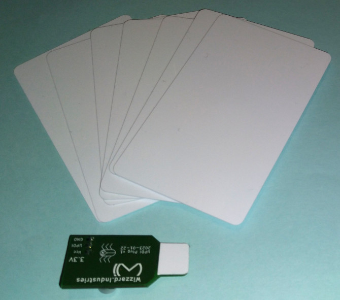
This means that about 0.8mm need to be added to this part of the PCB. Luckily most plastic cards (old credit cards, company badges, ski lift passes, google play vouchers, etc.) have a thickness of 0.75-0.85mm. Simply cut a 12mm square off an old card and glue it to the back of the plug. See Fig. 6 for an example.
You may need to sand off a bit in case your card or PCB have different thickness - test it with a USB socket.
Connector cable:
If you have a crimp set for Dupont style connectors it should be easy to create a simple connector cable with 3-pin connectors on one side and either 3-pin or single pin connectors on the other side. See Fig. 5 for some examples.
Depending on your needs you might also consider pogo pins for the microcontroller side of the cable. This avoids soldering pin headers to the microcontroller PCB just for programming. Instead the pogo pins are pushed onto the PCB just while programming the microcontroller. The examples in the figure were made by soldering pogo pins to the wires and then inserting them into an empty plastic shell for Dupont pins - I had to drill the holes a bit bigger and then used epoxy to fix the pogo pins in place.
The following table should help convert some of the units mentioned above.
| Metric | US customary |
| 0.8mm | 31mil or 1/32in |
| 1.6mm | 63mil or 1/16in |
| 2.4mm | 94mil or 3/32in |
| 2.54mm | 1/10in |
| 3mm | 118mil or about 1/8in |
| 6mm | 236mil or about 1/4in |
| 3.9mm | 150mil |
| 4.3mm | 170mil |
| 1.27mm | 50mil |
| 1608M | 0603 (SMD) |
| 2012M | 0805 (SMD) |
| 3.3V | 2 2/8 AA batteries |
| 5V | 3 1/3 AA batteries |
| 1kΩ | 2.2 pound Ω |
| 500Ω | about 1 pound Ω |
| 100nF | 3/16 tea spoons of electrons |
| 22µF | 1 3/64 lake Erie of electrons |
Dear Chinese (and other) Manufacturers.
Please feel free to copy this design. Build as many dongles as you like and flood the international market with them! The more, the merrier!
It's a really cheap and reliable design and it is about time the market gets flooded with UPDI compatible progger and debugger devices - just like the myriad USBasp clones are doing for the ISP protocol. This one is even easier: no firmware required.
For industrial manufacture I would recommend to either use a 2.4mm thick PCB to avoid the necessary adaptation of the USB plug thickness or to add a micro USB plug instead.